

Why this project exist?
I am making mobile robots for a while now, but the one thing which is still not changed in my journey is the use of those slow yellow colored BO Motors and their boring wheels. So, I wanted to change it and this is why I came up with the fastest, compact, inexpensive and 3D printed BO motors which I think is an amazing upgrade for my upcoming robots which will make my robots go faster.
Step 1: Brief about the project
So, here is a video to show what’s inside the project. I have created this little animation for better understanding.
Step 2: Gather the required tools and components
Wait, wait, wait. You don’t need anything out of this world. If you are a maker and are tinkering for a while now. You will find all of them in your arsenal.
Tools:
- 3D printer
- Allen keys
Components:
- Bo motor wheel
- BLDC Drone motor
- ESC to control the motor
- 11.1V 3S Lipo battery
- ESC tester
Step 3: 3D print the required parts
So, there are only 2 parts which are required to be 3D printed. The 1st part is the Hub of the motor and other is the mount using which you can attach it to the chassis of your robot. I’m using Prusa slicer to slice my models. It took 3hrs and 2 mins to print both the parts with 50% infill and 0.2mm layer height.

Download the files here: Coming soon….
Step 4: Modification
Before we use the motor in our project, we have to modify it and here is how we can do this step by step.
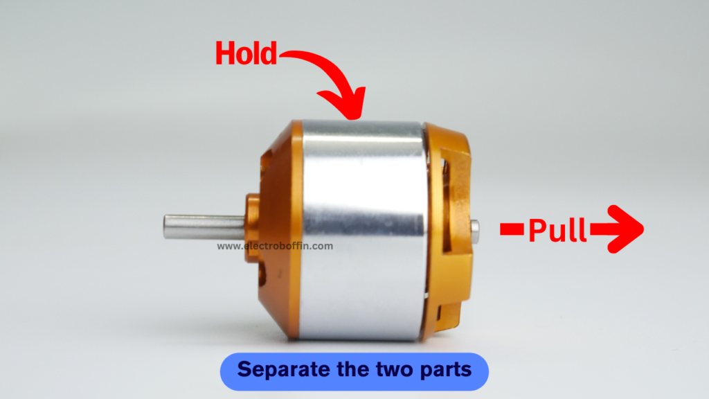
Firstly, we have to remove the shaft holding clip which is used to keep the prevention the detachment of top part when the propeller is attached on it due to thrust. Take a sharp object is pull it sideways. Without the removal of this clip, you won’t be able to separate the upper and lower half of the motor.

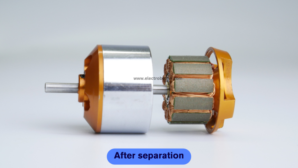
Now, you can easily pull the upper and lower half of the motor. Be careful while doing this because when you will try to pull the lower part out at the same time the magnets inside the motor will try to pull the lower part inwards as a result of which you may get harmed if your finger will be in between the upper and lower part.
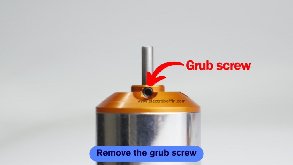
There is a grub screw that hold the shaft in place and prevent any dislocation of the shaft while working. We have to remove it because we have to adjust the height of the shaft.

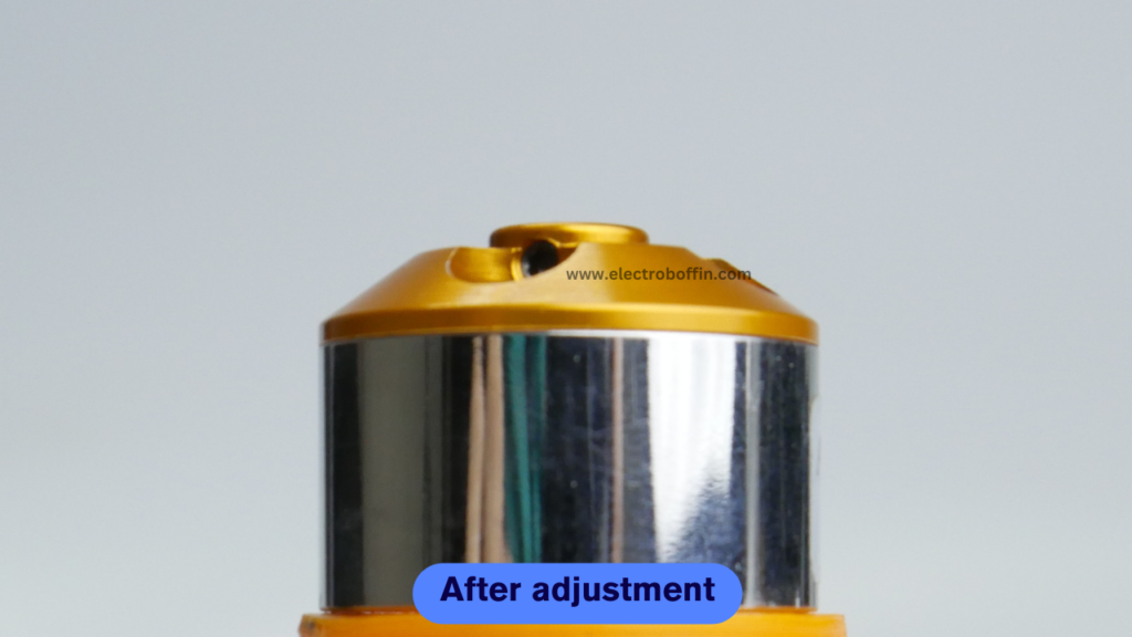
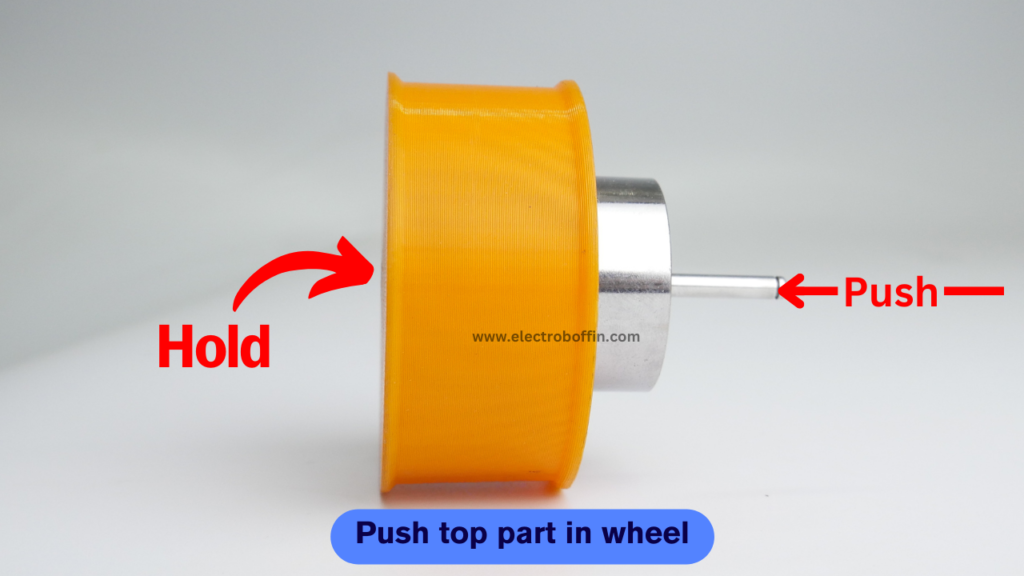
As, grub screw is now removed, you can place the upper part of the motor on the suitable surface so that the shaft can go down while pressing. You have to apply a lot of pressure here, I have used a hammer to do the same.

As the inner section of the motor will rotate at very high speed as a result of which the 3D printed part will not be able to move with it because we are not using any adhesive here. So, to make the 3D printed part move with the motor, I have added 4 support pins that will go inside the holes and help the 3D printed part move with the motor.

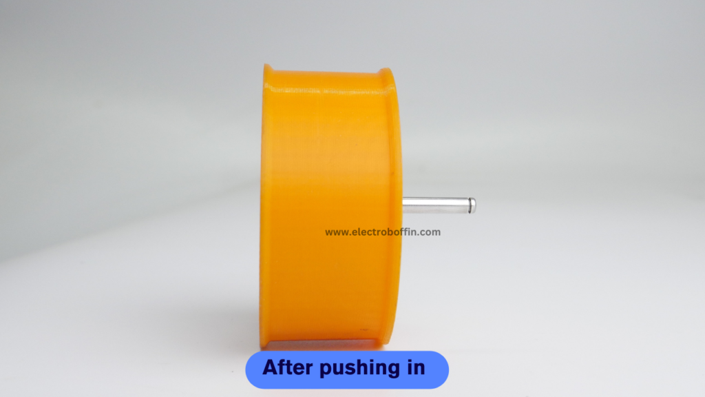
Once you have aligned the holes with the support pins, press the motor inside the 3D printed part.
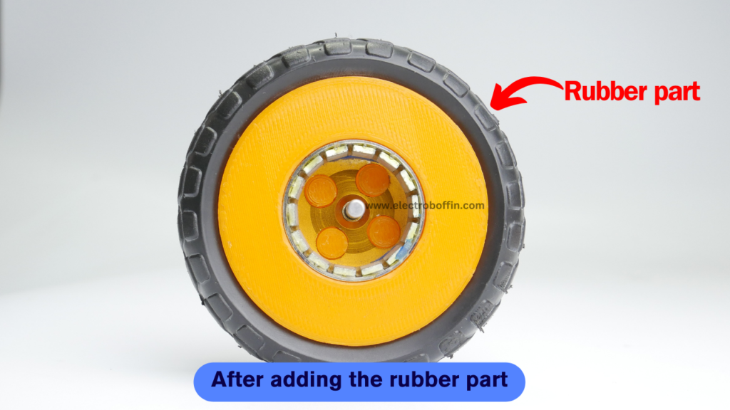
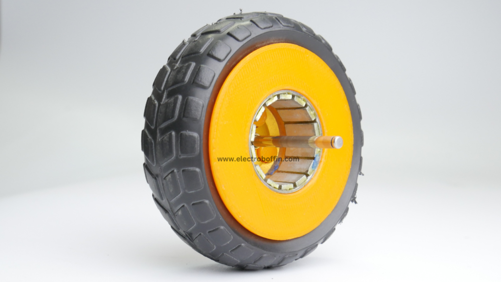
Now add the rubber part on the 3D printed part. I have removed the rubber part from an inexpensive BO Motor wheel which save my designing and printing time.
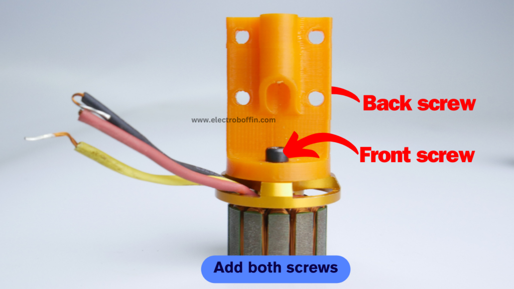
Notice the distance between the holes which are opposite to each other. One set of holes have shorter distance as compared to the other set. And we will be using this set with shorter distance to connect our 3D printed mount.

Place the 3D printed mount as mentioned above and add the screw that came with the motor.
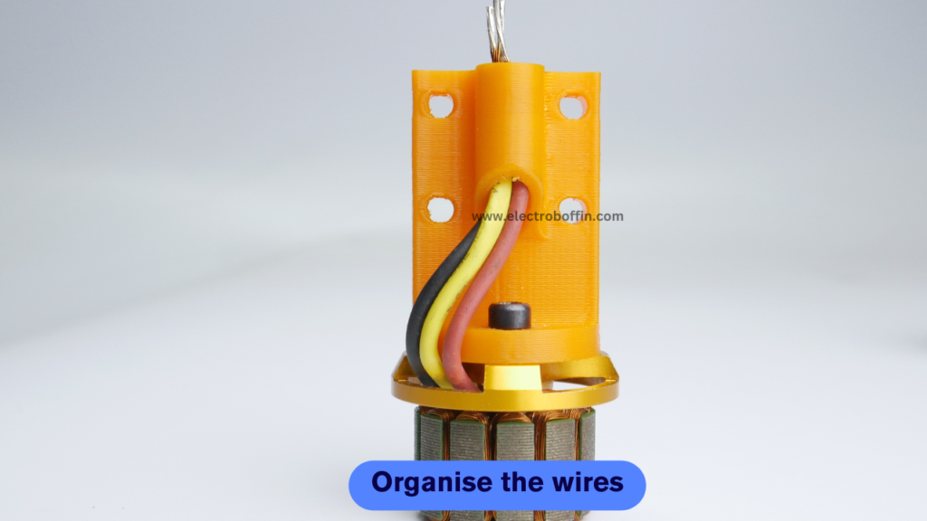
To avoid tangling of wires, pass the wires through hole as shown in image.
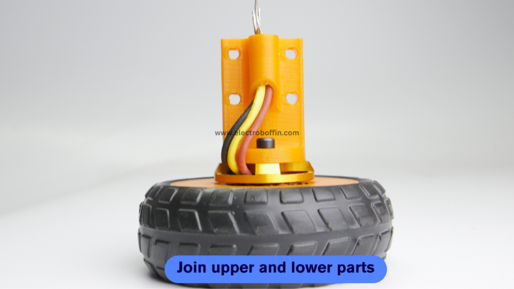
This is the final assembly step, join the upper and lower half and your wheel is now ready to rock on.
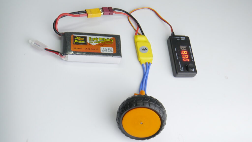
This is how my test setup looks. Simple and elegant.✨
Working of the project
How I calculated the RPM?
RPM = KV of motor X Battery voltage = 1400KV X 11.1V = 15540.
Why I am operating it at 50% ?
As I am holding the wheel in my hand and I don’t want to kill myself because it needs a lot of force to hold it😂
Possible Issues and resolution
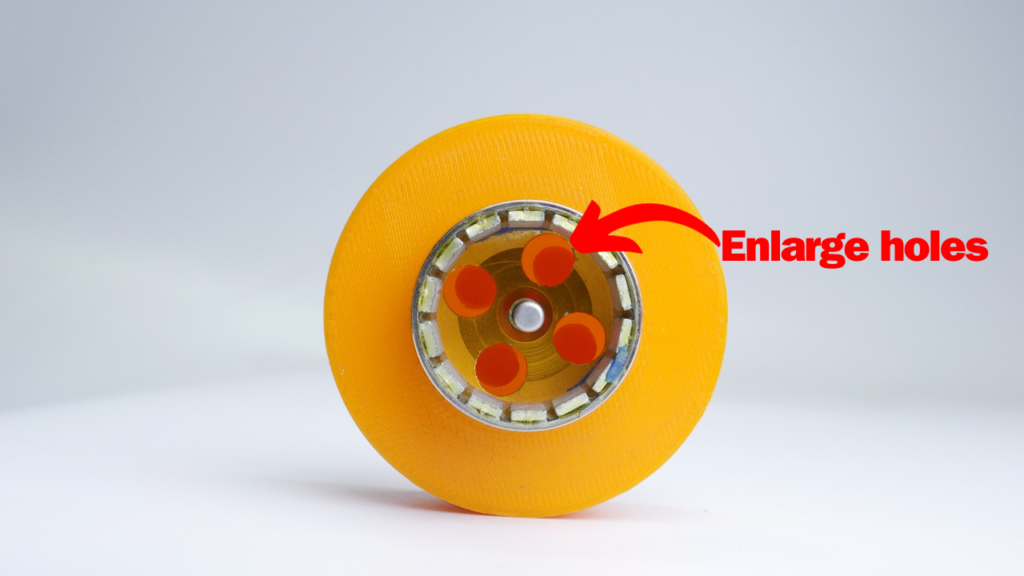
Issue 1 resolution: There are a lot of different types of this cheap motor available in the market, the major difference comes in the size of the holes near the top surface. If your motor has smaller size of holes, take a drill and enlarge it a bit or find another motor 😉
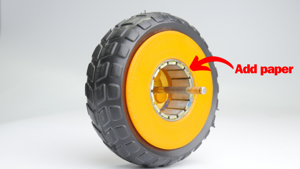
Issue 2 resolution: If the motor is loose inside the 3D printed part, add a small piece of paper, and you are good to go.
Featured on:
This project has been featured on various platform, please visit “In Media” section to see where this project has been featured